Saturday 12 February 2011

Aircraft build - Under carrage

Tyres
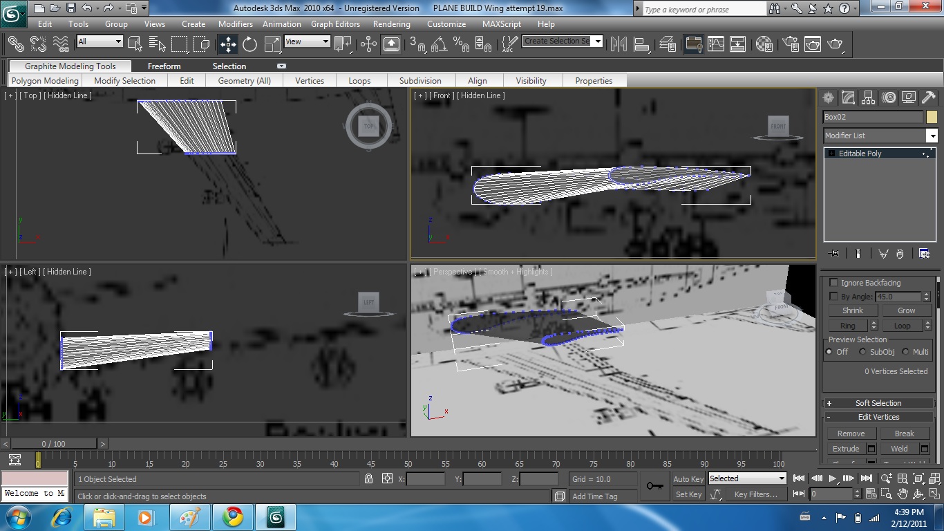
standard primatives - cone - size using reference planes


Editable poly - edge - loop select both sides - scale - drag inwards


Turbo smooth


Select edge - loop - select second loop - scale in
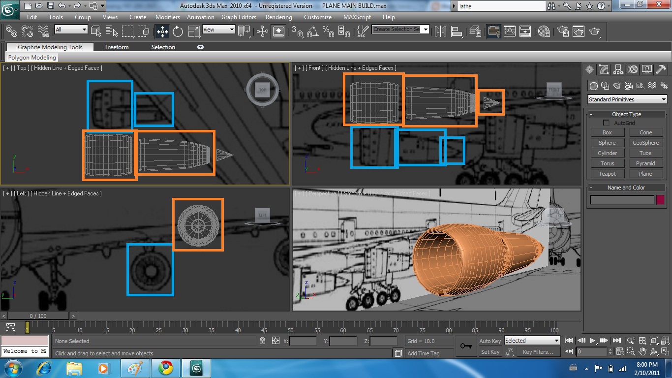


Wheels

Cylinder - line up geometry with tyre - hide tyre - [height segments 1] [cap segments 3]


Editable poly - select edge - loop - scale


Select poly - move geometry backwards - FIND OUT DOESNT WORK - REPEAT PROCESS USING CAP SEGMENTS 5


Repeat process - next slide showing intended result with materials + turbo smooth + attached to tyre


Tools - mirror - offset 1.0 - y axis - instance (so changes apply to both)


Cylinder to bridge gap - attach


Tools - mirror - add cylinder to bridge gap


Copy - instance


Extend undercarriage support arm up to fuselage. Select polygon that would intersect. 


Extrude - inset - move polygons back into fuselage leaving square tube.


 Remove front / rear sides of tube. Bridge gaps in remaining tube sections. Extend undercarriage arm up into fuselage


Reposition rear gears to mimic 747 positions. Begin enhancing appearance. Support leg change from single cylinder to larger diameter on top of smaller diameter cylinder (raise cylinder - select bottom polygon - inset - extrude) - create clones and rescale + position to create more realistic appearance


Select polygons where undercarriage doors would be - this will allow a reference point when flicking between vertex + polygons because selections are saved


Manipulate vertex to create more accurate door profile.


Detach - extrude for thickness


Rotate into position


Aircraft build - Tail fin

Take earlier made centre rudder - highlight - right click - clone
move clone into position


rescale - manipulate - vertex to create new shape


Aircraft build - Fuel Pod

Research pic


http://www.warbirdphotographs.com/Harada/H-Zero-DropTank-35.jpg


Create profile - lathe - cap ends - stretch - scale - turbo smooth -  position - attach


Aircraft build - Wing

Wing
Draw profile using reference planes
turn into edit able poly


Clone poly - move to second position (where wing geometry changes) - bridge


Repeat to end of wing


With this technique however discovered bridge had inverted to end of wing - geometry intersected with self


Upon several attempts unable to rectify - started again

Wing attempt 2

Draw profile - turn into editable poly


Extrude poly and manipulate into shape


Extrude poly and manipulate again


Thursday 10 February 2011

Aircraft build - Engines

Create tube - align with front part of engine - turn into editable poly - shrink front and back to generate smooth curve


Trace profiles from outer engine / back of engine from reference planes - Turn into editable poly - Use lathe technique as before (360') to create pieces to slide together


Move into position and align with reference planes to check for accuracy
Slide into over lapping positions to create engine base


TURBINE

Create tube - thin with hole in middle - take measurements from reference planes - Lots of sections required


Turn into editable poly - Remove all geometry except single segment - Select boundry on open segments and select cap


Twist outside geometry


Select tools - array - change appropriate boxes to produce 30 blades overlapping over 360'


Add cone to centre to give impression of  turbine blades + turbine


Aircraft build - Vertical stabilizer - basic build

Draw basic cube. Add segments to allow for manipulation (6x6x2)


Convert to editable poly
Highlight and remove all internal details. (using drag select will select all points through object)


right click - object properties - see through - select yes
Manipulate edge vertices to align with with reference planes


Remove uneccessary verticies - apply smooth to soften harsh angles


Aircraft build - Fuselage - basic shape

Draw line representing half of profile (top down)
Enter modifier tab - modifier drop down box - select LATHE.


Once in lathe mode - adjust axis position and if necessary direction of rotation to generate fuselage


Move shape into position to align with all three reference planes
Select vertices and manipulate into fuselage shape using different viewpoints


Apply turbo smooth to enhance shape


Aircraft Build - Research + Planning - Skyfleet S570

Researched into plane model - Fictional plane based on decommissioned 747 - 200B with modifications to body shape for new look in film


SKYFLEET S570
http://www.notarealthing.com/2010/09/skyfleet-and-texron

747 - 200


http://www.aviationnews.eu/aircraft-fact-sheets/civil-aircraft-fact-sheetszap16com/boeing-747-200/

Found 747 - 100 2D scaled perspective drawing to use.
Will use these drawings for basic reference then modify design accordingly


http://www.hobby-bench-buddy.ca/BetterFly2/RC_plan_JETS_3view.html


Reference bitmap (jpeg) size
in 3ds max - standard primatives -  plane - changed size of plane to same as bitmap scaled down (eg 1590 = 159.0 etc)


add other 2 perspectives - align - freeze into position (after deselecting turn frozen objects grey in object properties)


Right click to access object properties

Also may need to access top bar - customize - preferences - configure drivers - tick boxes to allow bitmaps to be displayed in high resolution


if does not work initially - save file, exit and reload.